 | |
| The Aperture will be mounted to the two black cubes which also hold the poles for the flat mirror. |
 |
| Here is a side view of the entire model. You can see here to location of the projector and at which angle the rays will fall onto the screen. The convex mirror profile was chosen to maximise coverage. |
Because we are cutting a plane through a cone at an angle we will need an eliptical opening. Now, if you are a straight A student you'll know how to calculate the dimensions of the eliptical cross section at the level of the intersecting plane. But if you are, like me, a lazy git, you'll just punch it into the modelling software and make the computer do the work.
First of all, we take the projector output and revolve it around the centre axis to get a solid body which we can use for modelling. With that you can create a plane in the desired orientation and level as I've done in the picture below. For clarity I made the raytracing lines invisible. You can probably guess where I'm going with this now.
 |
| By taking the raytracing lines and revolving them around the centre we can make a 3-dimensional representation of the projector output. |
Next step is to slice the model at the level of the plane. Sounds like a lot of work but really all you need to do is hit F7.
 |
| The cone sliced by the plane. |
Now all you have to do is project the cut edges of the cone onto your plane, create a sketch and extrude it.
 |
| Sketching a simple rectangle with the ellipse projected at its centre. |
 |
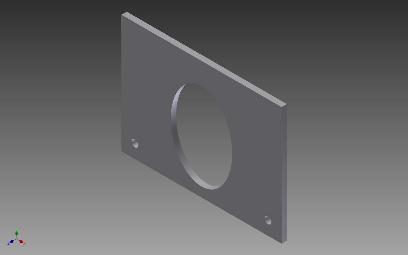
| The extruded aperture with the requried opening. |
 |
| Aperture mounted to construction cubes with bolts. |
To turn the computer model into reality we can easily create a technical drawing which can be handed to the workshop. With sufficient annotation they should be able to create the desired part.
 | ||
| Technical drawing of the Aperture. |
EDIT:
Just a few words of clarification:
- the light cone cuts through the flat mirror, that is just me being too lazy to correct the model. I simply revolve the top half of the lightpath around the central axis, but because the cone is at an angle to the mirror it will cut through it.
- the initial technical drawing missed a few annotations, that is now corrected.
No comments:
Post a Comment